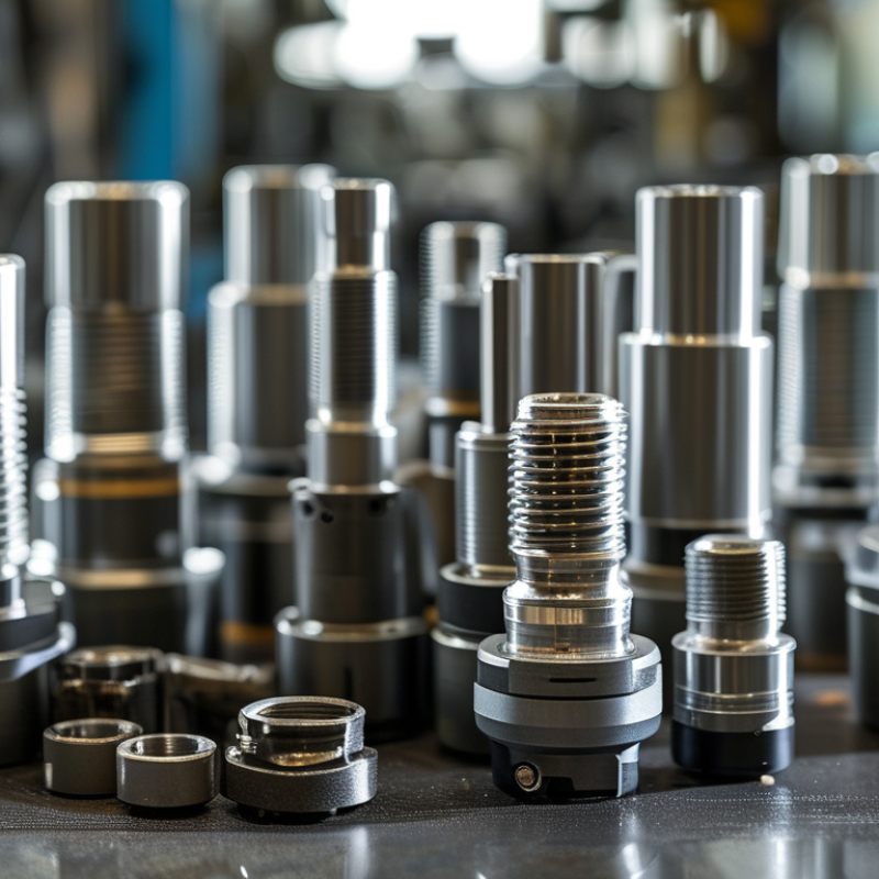
| External Threaded End | A male thread is machined directly onto the outside diameter of the shaft end. A nut, coupling, or threaded component is installed over it. | Fasteners, rollers, wheels, pulleys, linkages, actuator assemblies, and general rotating equipment. | Metric ISO coarse or fine threads; Unified coarse or fine threads; other national standards where specified. | Simple construction, economical machining, compact axial fastening, and easy compatibility with standard nuts. | Specify major diameter, pitch, thread length, end chamfer, shaft diameter, material, and required fit. Allow sufficient unthreaded shoulder length for seating. |
| Internal Threaded End | A female thread is machined into a drilled hole at the shaft end. A bolt, stud, or threaded adapter engages inside the shaft. | Removable hubs, instrument mounts, compact couplings, fixtures, and assemblies where an external thread would interfere with surrounding parts. | Metric ISO; Unified inch series; pipe threads only when the connection is intended for fluid service. | Clean external profile, protected thread location, and good suitability for compact assemblies. | Check minimum wall thickness, thread engagement length, pilot-hole depth, bottom relief, and the risk of reducing torsional strength at the shaft end. |
| Stepped Threaded End | The shaft transitions through two or more diameters, with the thread located on a smaller or larger section and a shoulder used for axial positioning. | Bearings, sprockets, gears, pulleys, wheels, and components requiring a positive locating surface. | Metric or Unified machine threads selected according to the nut, load, and available shaft diameter. | Provides a reliable shoulder stop, improves component location, and separates the bearing or hub seat from the fastening thread. | Control shoulder squareness, transition radii, thread runout, and the diameter ratio between the loaded shaft section and the threaded section. |
| Shouldered Threaded End | A precision shoulder is positioned immediately behind the threaded portion so a component can seat against a defined axial reference. | Precision shafts, bearing assemblies, encoder mounts, gear trains, and rotating parts requiring controlled axial position. | Metric ISO or Unified machine threads; tolerance and shoulder specifications depend on the required fit. | Improves axial repeatability, reduces component movement, and supports accurate bearing or hub positioning. | Specify shoulder diameter, shoulder width, perpendicularity, concentricity, thread relief, and surface finish of the seating area. |
| Left-Hand Threaded End | The thread tightens in the counterclockwise direction when viewed from the threaded end, opposite to a conventional right-hand thread. | Rotating assemblies in which normal rotation could loosen a right-hand fastener, including selected fan, spindle, and rotating-tool arrangements. | Metric or Unified left-hand thread designation, normally identified with an explicit left-hand marking. | Helps resist self-loosening caused by the direction of rotation or applied torque. | Confirm rotation direction, thread hand, mating nut availability, marking requirements, and assembly instructions before production. |
| Double-Ended Threaded Shaft | Both ends of the shaft include threaded sections. The center section may be plain, keyed, splined, or machined for a bearing or coupling. | Linkages, tie assemblies, tension systems, opposed fixtures, and mechanisms requiring fastening from both sides. | Matching or different metric and Unified threads may be used, provided the drawing clearly identifies each end. | Supports two-sided fastening, flexible installation, and compact connection layouts. | Define the thread length and hand at each end, center-section diameter, overall length, runout, and minimum unthreaded distance. |
| Fine-Threaded Shaft End | Uses a smaller thread pitch than a comparable coarse thread, giving more threads per unit length and finer axial adjustment. | Adjustment mechanisms, precision preload, thin-wall nuts, vibration-sensitive assemblies, and applications with limited axial space. | Metric fine-pitch threads or Unified fine and extra-fine series. | Provides finer axial movement per turn, greater preload adjustment resolution, and a larger minor diameter than a coarse thread of the same nominal size. | Fine threads are more sensitive to damage and contamination. Check installation torque, cleanliness, thread protection, and stripping resistance. |
| Tapered Threaded End | The threaded diameter changes gradually along the thread length, allowing the mating tapered thread to tighten through wedging contact. | Fluid or pressure connections when a recognized tapered pipe-thread system is specifically required. | Examples include ISO 7-1 pipe threads and ASME B1.20.1 pipe-thread forms, subject to the selected system and region. | Can create a compact pressure connection without a separate flange when correctly selected and assembled. | Do not substitute a tapered pipe thread for a straight mechanical shaft thread. Verify pressure rating, sealing method, thread standard, engagement, and compatibility with the mating port. |
| Threaded End with Keyway or Cross-Hole | Combines a threaded end with an additional keyway, radial hole, or axial feature for torque transmission, locking, or alignment. | Hubs, levers, pulleys, sprockets, locking assemblies, and components requiring both axial retention and torque transfer. | Metric or Unified machine threads with keyway or hole dimensions defined on the engineering drawing. | Combines fastening and torque-transfer functions in one shaft-end design. | Check stress concentration around the keyway or hole, edge distance, thread runout, locking method, balance requirements, and fatigue loading. |
| Reduced-Diameter Threaded End | The threaded portion has a smaller diameter than the main shaft, creating a transition between the working shaft and the fastening section. | Axial retention of bearings, wheels, rollers, spacers, and lightweight rotating components. | Metric ISO or Unified machine threads selected according to the available end diameter and applied load. | Leaves a larger shaft surface for the working component while providing a compact fastening area. | Use a generous transition radius where possible, evaluate fatigue strength, and avoid excessive thread length that could weaken the reduced section. |