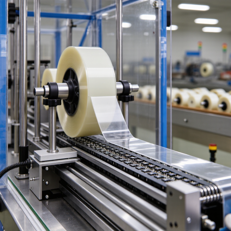
| Carrier Tape Compatibility | Select cover tape specifically matched to the carrier tape material, pocket geometry, and sealing layer. Common carrier materials include embossed polymer tape and paper-based tape. | The cover tape must seal continuously over the carrier-tape sealing area without interfering with sprocket holes or component pockets. | Confirm the carrier-tape material, sealing surface, tape width, pocket pitch, and recommended sealing temperature before qualification. | Review the carrier-tape drawing and perform a production-speed sealing trial using the intended equipment. |
| Nominal Cover Tape Width | Common nominal widths include 5.4, 9.3, 13.3, 17.3, 21.3, 25.5, 37.5, 48.4, and 56.5 mm. | The selected width must provide adequate sealing land on both sides of the carrier-tape cavity while maintaining clearance from sprocket holes. | Choose the width specified for the selected carrier-tape format rather than selecting solely from the component size. | Measure tape width and inspect the sealed web for uniform edge coverage across the full reel. |
| Tape Construction | Typical construction consists of a polyester or polyolefin support film with a heat-seal or pressure-sensitive sealing layer. | The sealing layer must be compatible with the carrier-tape surface and must not leave excessive residue after peeling. | Use heat-activated tape for controlled thermal sealing; consider pressure-sensitive tape where the carrier and process are qualified for that system. | Check the supplier technical data sheet, cross-section, seal initiation temperature, and residue after peel. |
| Sealing Temperature | A practical qualification window is commonly established around 120–180 °C, depending on the sealing layer, carrier material, line speed, and dwell time. | EIA-481 defines packaging performance requirements, but the optimum process temperature is dependent on the tape and carrier combination. | Start with the tape supplier's recommended range and qualify the lowest temperature that produces a continuous, secure seal. | Record heater temperature, actual seal-bar temperature, dwell time, pressure, line speed, and peel results. |
| Peel Strength | Use the applicable EIA-481 revision and customer specification for the acceptance limit. A commonly used qualification target for many component-packaging systems is approximately 0.2–1.0 N peel force. | The cover tape must retain components during handling and transport but still peel in a controlled manner during automatic component placement. | Avoid both weak seals, which may open during shipment, and excessive seals, which can cause component ejection, tape tearing, or feeder stoppage. | Perform a controlled peel test at the specified angle and speed. Report average force, peak force, failure mode, and test direction. |
| Peel Behavior | The preferred result is a smooth, continuous peel with no sudden release, tearing, stringing, or adhesive transfer. | Stable peel behavior supports reliable automatic feeding and helps prevent component movement or loss from the pocket. | Select a tape with consistent peel force across the beginning, middle, and end of the reel. | Inspect peel force at multiple reel locations and observe the tape during operation at the maximum intended feed rate. |
| Anti-Static Performance | For electrostatic-sensitive devices, specify a static-dissipative or antistatic cover tape with surface resistance and charge-generation limits defined by the packaging requirement. | The cover tape should not create a damaging electrostatic discharge when peeled, handled, or processed through an automatic feeder. | Use an ESD-control packaging system when the component handling specification requires it; do not rely on color or appearance as proof of ESD performance. | Measure surface resistance and charge generation using the applicable ESD test method under controlled temperature and humidity. |
| Transparency and Inspection | Transparent or translucent film is preferred when visual inspection of component presence, orientation, and pocket fill is required. Opaque film may be used for light-sensitive or confidential components. | The cover tape must allow reliable inspection without causing optical distortion that hides missing, tilted, or damaged parts. | Choose transparency based on the component body, marking contrast, inspection camera, and lighting conditions. | Verify inspection accuracy using filled, empty, misaligned, and damaged-pocket samples. |
| Film Thickness and Flexibility | Typical cover-tape film thickness is approximately 30–100 μm, depending on construction and required stiffness. | The tape must conform to the sealing surface while remaining strong enough to resist tearing and wrinkling during winding and feeding. | Use thinner film for flexibility and optical access; use a more robust construction when puncture resistance or high-speed handling is critical. | Measure thickness, inspect for wrinkles, and run a full-reel winding and feeding trial. |
| Seal Uniformity | The seal should be continuous across both sealing edges, without channels, skips, bubbles, folds, or localized delamination. | Consistent sealing is essential for component retention during reel winding, transportation, and automated feeding. | Control sealing-bar flatness, pressure, temperature distribution, carrier-tape tension, and web alignment. | Perform visual inspection, peel testing, and periodic cross-web checks at the left, center, and right sealing areas. |
| Moisture and Humidity Exposure | Qualify the tape at the intended storage and operating conditions. A common laboratory conditioning point is approximately 23 °C and 50% relative humidity, unless another condition is specified. | Temperature and humidity can change adhesive behavior, peel force, film stiffness, and seal integrity. | Include both normal and worst-case environmental conditions in validation, especially for long storage or overseas transportation. | Condition samples before testing and compare seal strength, peel behavior, and appearance before and after environmental exposure. |
| Storage Life | Store unused reels in the supplier's recommended sealed packaging and within the stated temperature and humidity limits. A typical controlled storage range is approximately 15–30 °C. | Long-term exposure to heat, moisture, dust, and direct sunlight can affect the sealing layer and peel performance. | Use first-in, first-out inventory control and define a retest period for material approaching its recommended shelf life. | Retest aged material for seal strength, peel consistency, visual condition, and feeder performance before release. |
| Reel and Splice Quality | Reels should be wound evenly, free from telescoping and crushed edges, and clearly identified with lot, width, length, and manufacturing information. | Poor winding or uncontrolled splices can cause interruptions, feeder jams, or loss of positional accuracy. | Define maximum splice frequency, splice construction, splice visibility, and splice strength in the purchasing specification. | Inspect reel edges and run the complete reel, including splice areas, through the production feeder. |
| Residue and Cleanliness | The peeled cover tape should leave no visible adhesive residue, particles, fibers, or coating transfer on the carrier tape or component. | Residue can contaminate components, affect soldering or assembly, and interfere with pocket inspection and feeding. | Select a low-residue formulation and qualify it with the actual component finish and carrier-tape material. | Inspect peeled surfaces under suitable lighting and, where necessary, use microscopic or chemical contamination analysis. |
| Process Documentation | The approved specification should identify cover-tape width, construction, sealing temperature, pressure, dwell time, peel criteria, storage conditions, and lot traceability. | EIA-481 compliance depends on the complete carrier-tape and cover-tape packaging system, not on the cover tape alone. | Freeze the validated process window and document any change to material construction, coating, supplier, or manufacturing site. | Maintain incoming inspection records, process capability data, peel-test results, and change-control documentation. |
| Final Qualification Decision | Accept when retention, peel, ESD, cleanliness, inspection, and feeder performance meet the approved specification.
Reject when any critical requirement fails or performance is unstable across the reel. | Qualification should represent the complete packaging process and the actual production environment. | Approve the tape only after testing with production equipment, representative components, intended carrier tape, and expected environmental conditions. | Issue a documented qualification report with sample size, test conditions, measured results, deviations, and approval status. |